Article From: 11/28/17 Advanced Manufacturing, Ilene Wolff, Contributing Editor
… For use with CFRP-reinforced materials, RobbJack Corp. (Lincoln, CA) has a polycrystalline diamond, “W”-tipped drill.
“We’re able to flute diamond now like carbide using electrical discharge grinding,” said Mike MacArthur, vice president of engineering. “And that’s very new technology that’s allowed us to get all the advantages that you could grind in carbide but now in a solid piece of diamond.”
In the past, MacArthur explained, you either had to have a flat plane of diamond that was brazed into carbide or grind a path and then sinter diamond into a thin area of a tool.
“Now we can take a solid nib of 100% polycrystalline diamond and we can actually grind it like you would carbide,” he said.
To read the full article, click here.
Article from: Cutting Tool Engineering, 7/14/2020 by Alan Richter
When a workpiece material is relatively easy to machine and a wide range of parts are made of it, a large number of part manufacturers will machine it. As a result, shops must achieve a high level of productivity to remain competitive, and that’s certainly the case with aluminum alloys.
“For the customer, it’s all about how many cubic inches of material they remove per minute,” said Mike MacArthur, vice president of engineering for RobbJack Corp., Lincoln, California. “The more chips they get out as fast as possible, the more money they are going to make.”
“We even have a customer that is cutting so much aluminum that they have cut holes in a wall of the machine,” MacArthur said, adding that the wall was replaced but not the machine. “It sounds like a machine gun going off when they’re cutting aluminum.”
Read the full article HERE…

Article From: 11/22/17 Modern Machine Shop, Mark Albert, Editor-in-Chief
In a machining process, vibration causes chatter. More specifically, chatter occurs when the workpiece and the cutting tool are vibrating at different frequencies. Literally, the workpiece is moving in one direction while the cutting tool is moving in the other direction. Of course, these relative motions are slight and happen at many times a second. Chatter is the resultant sound of the workpiece and the cutting tool knocking into one another at a high rate. This knocking does more than make an irritating noise: It also damages the tool, degrades the workpiece surface, harms the spindle and may leave part features out of tolerance.
Cutting tool manufacturer RobbJack has a strategy for dealing with chatter that is based on the concept of getting the cutting tool and the workpiece to vibrate in the same direction at the same rate. To this end, the company has developed an end mill design (primarily for milling aluminum at high feed rates) that gets the cutter and the workpiece to synchronize the frequency of vibrations during machining. This does not stop the vibration, but rather stops the knocking caused by out-of-sync vibrations. Apparently, when the knocking goes away, so do the other unwanted side effects.
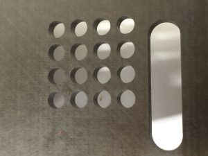
Mike MacArthur, vice president of engineering at RobbJack, explains that the end mill design includes a special edge preparation that creates an additional surface along the trailing side of each spiraled flute. The company calls this additional feature the Mirror Edge, because it is highly polished and shiny. This added edge is 0.001- to 0.002-inch wide, so it can barely be discerned by holding the tool and slightly turning it in the light. The first photo in the slideshow above captures the slender band of light reflected by this edge as indicated by the arrow. The other reflections alongside it are, respectively, the land and the cutting edge of the flute normally found on a spiraled end mill.
Mr. MacArthur says this added edge is just enough to keep the flute in contact with the workpiece until the next flute is engaged (the end mill has three tightly spiraled flutes for this reason). This highly polished edge minimizes frictional rubbing, so it creates virtually no heat and does not alter the workpiece surface. The constant contact prevents both the tool and the workpiece from “going their separate ways” in response to various forces inducing vibration. Thus, the tool and workpiece keep moving in unison to maintain synchronization regardless of the frequency of the vibration. Neither the tool nor the workpiece can “bounce away” from the other and fall into a different rate (frequency) of vibration, Mr. MacArthur says.
This out-of-sync condition can occur instantly, and once it starts, the tool and workpiece begin bouncing off one another more forcefully with each passing of the flutes across the workpiece. This worsening condition is detectable as chatter. “A machinist can hear the rise and fall in the sound of this chatter as the frequencies go in and out of phase,” he says.
Keeping vibration in sync to avoid negative consequences does impose certain requirements on the machining process. According to Mr. MacArthur, the tool must be used with flood or through-tool coolant to keep chips from interfering with the action of the Mirror Edge. The tool works best in aluminum, because the high spindle speeds used for cutting this material tend to create higher cutting frequencies than those encountered at lower spindle speeds when machining harder materials such as steel or titanium. (However, Mr. MacArthur notes that the Mirror Edge can be added to end mills customized for specific applications in these materials, although other vibration-control techniques are likely to be needed for full effectiveness in these cases.) End mills with Mirror Edge can be used at the machine tool’s highest spindle speed in aluminum without any chatter. This enables the feed rate and metal removal rate to increase substantially. Stepovers that are 50 percent of the tool radius are recommended, along with chip loads equal to the tool diameter times 0.016-inch per flute.
Mr. MacArthur says that applications with deep pockets and/or thin walls are the most suitable for these end mills, however, certain programming techniques are in order for machining thin walls. For example, each Z level of a pocket should be roughed and finished before proceeding to the next, lower Z level. Sufficient stock should be left on the walls for the finishing pass to maintain rigidity. This stock helps support the wall ahead of the cut. Applying constant-chip-load pocketing routines in the CAM program is also recommended. He says walls as thin as 0.005 inch and as tall as 3 inches can be produced effectively in this manner. The resulting wall will be straight and smooth.
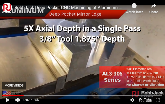
Perhaps a more significant benefit is the substantial increase in metal removal rates that Mr. MacArthur reports for these end mills in aluminum. “A fivefold increase in metal removal rates compared to traditional end mills is possible,” he says. “Removing as much is 42 cubic inches of material per minute can be attained with significant increases in tool life to boot,” he adds, noting that walls thinner than 0.020 inch limit removal rates to accommodate the smaller stepdowns in Z that are required.
Currently, the Mirror Edge preparation is available on RobbJack’s A1-303 and FM series aluminum end mills in diameters from 1/8 to 1 inch on standard tools, and on tools as small as 0.010 inch in diameter on special order.

Machine tools designed for milling titanium are generally characterized as having heavy, rigid structures with spindles designed for high torque at low spindle speed. Large spindle tapers and high-pressure coolant are also typical. For multi-axis work, a beefy trunnion and rotary table may be provided as well.
Click HERE to read the full article
Article From: 10/1/2015 Modern Machine Shop, Mark Albert , Editor-in-Chief


Extensive research has gone into developing the speed and feed recommendations found in this online calculator. This speed and feed program is designed specifically for use with RobbJack tools. Tools made by other manufacturers may not be able to run at the same speeds and feeds recommended for ours.
The recommendations in this speed and feed program are a maximum limit and are based on ideal conditions. These speeds and feeds should be considered a starting point for machining. The user must take into consideration the rigidity and capability of the machine tool, part geometry, and fixturing to determine if the recommended speeds and feeds should be adjusted based on machining conditions.
We have made efforts to ensure that the information in this program is clear and accurate and shall not be held responsible for any inadvertent errors in content or interpretation or application of the information. Use of the program indicates consent to and agreement with the End User License Agreement.

If you have any problems using the program or if you get questionable results please contact the RobbJack Applications Department at 800.527.8883.